Bio 3 Biodiffuser Cluster Installation Detail
Filename:
Bio 3 Biodiffuser Cluster Installation Detail.dwg

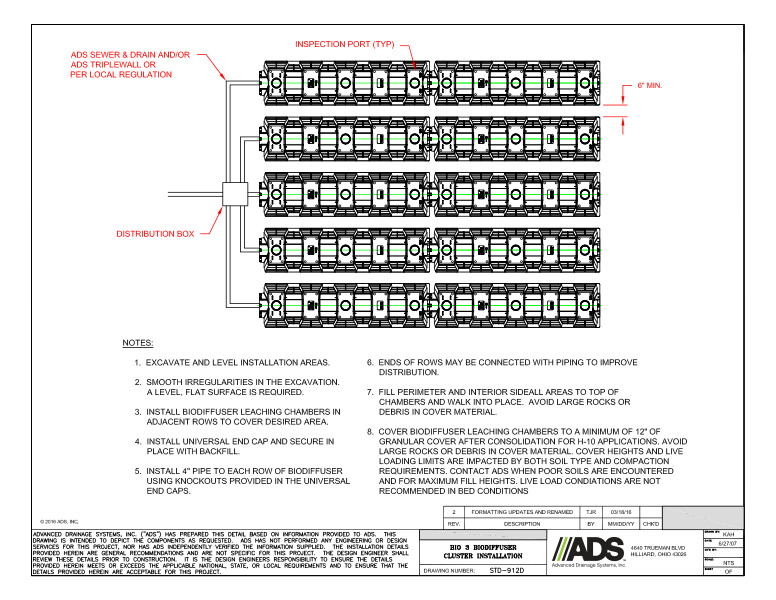
This document is Bio 3 Biodiffuser Cluster Installation Detail. A diagram with descriptors and notes explains the biodiffuser cluster.
This biodiffuser cluster diagram shows the ADS sewer & drain and/or ADS triplewall OR per local regulation, inspection port (TYP), distribution box and 6” minimum.
Notes explain installation with directions to excavate and level installation areas. Smooth irregularities in the excavation because a level/flat surface is required. Install biodiffuser leaching chambers in adjacent rows to cover desired area. Install universal end cap and secure in place with backfill. Install 4” pipe to each row of biodiffuser using knockouts provided in the universal end caps. Ends of rows may be connected with piping to improve distribution. Fill perimeter and interior sidewall areas to top of chambers and walk into place. Avoid large rocks or debris in cover material. Cover biodiffuser leaching chambers to a minimum of 12” granular cover after consolidation for H-10 applications. Avoid large rocks or debris in cover material. Cover heights and live loading limits are impacted by both soil type and compaction.
