113 HDPE & PP Connection to Concrete Headwall Detail
Filename:
113 HDPE & PP Connection to Concrete Headwall Detail.pdf

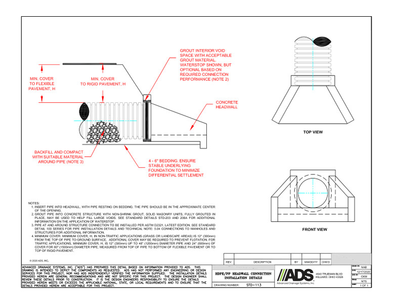
This document is the drawing for the 113 HDPE & PP Connection to Concrete Headwall Detail, showing how to connect the pipe to the concrete headwall.
The 113 HDPE & PP Connection to Concrete Headwall is a drawing showing how to connect the drainage pipe to the concrete headwall. The drawing illustrates the minimum cover to flexible pavement height and minimum cover to rigid pavement height. It is recommended to grout the interior void space with acceptable grout material. The waterstop is shown, but is optional, based on required connection performance. It also shows where the backfill goes, with the recommendation to compact with suitable material around the pipe.
The steps indicate to insert the pipe into the headwall with the pipe resting on the bedding. The pipe should be in the approximate center of the opening. Grout pipe into concrete structure with non-shrink grout, solid masonry units, fully grouted in place, may be used to help fill large voids. See standard details STD-203 and 206A for additional information on the application of waterstop.
The pipe at and around the structure connection needs to be installed per ASTM D2321, latest edition. See standard detail 100 series for pipe installation details and Technical Note 504: Connections to Manholes and Structures for additional information.
The minimum cover height in non-traffic applications (grass or landscape areas) is 12” (300mm) from the top of the pipe to the ground surface. Additional cover may be required to prevent flotation. For traffic applications, minimum cover height is 12” (300mm) up to 48” (1200mm) diameter pipe and 24” (600mm) of cover for 60” (1500mm) diameter pipe, measured from top of pipe to bottom of flexible pavement or to top of rigid pavement.
