Nyloplast Water Control Structure Detail
Filename:
Nyloplast Water Control Structure Detail.dwg

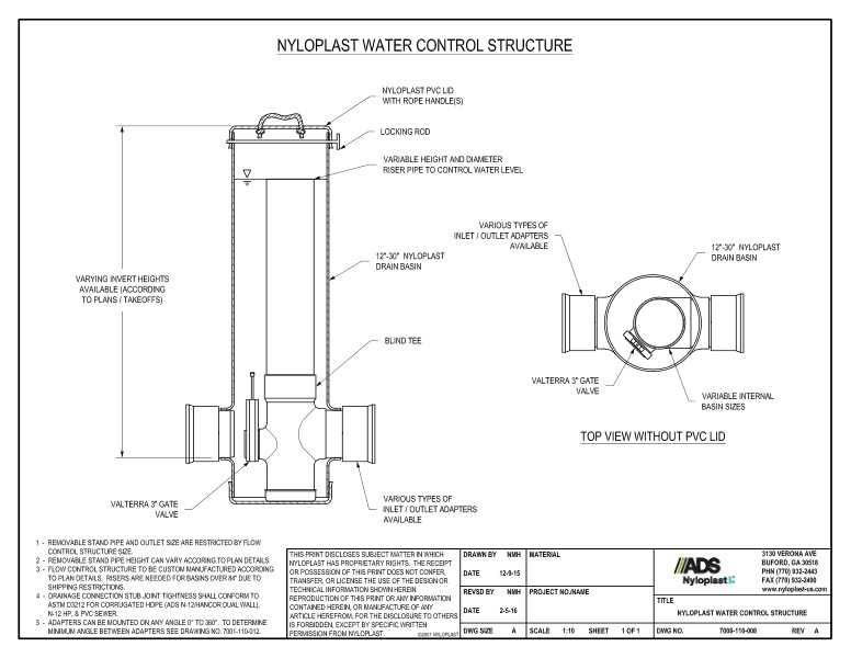
This document is the Nyloplast Water Control Structure Detail. Details and nyloplast illustration shown.
The Nyloplast Water Control Structure Detail shows the nyloplast PVC lid with rope handles, locking rod, variable height and diameter riser pipe to control water level, 12”-30” nyloplast drain basin, blind Tee, variable invert heights and inlet/outlet adapters and a Valterra 3” gate valve. Top view shows the various types of inlet/outlet adapters, 12”-30” nyloplast drain basin, a Valterra 3” gate valve and variable basin sizes.
Note 1 states that removable stand pipe and outlet size are restricted by flow control structure size. Note 2 says that removable stand pipe height can vary. Note 3 states that flow control structure must be custom manufactured. Note 4 outlines drainage connection stub joint tightness conformities. Note 5 states that adapters can be mounted on any angle.
