201 Structure Connection Installation Detail
Filename:
201 Structure Connection Installation Detail.dwg
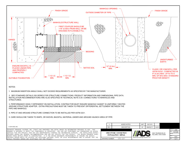
This document is the 201 Structure Connection Installation Detail. Side and front view diagrams with descriptions and notes provided.
The side view diagram shows the finish grade, manhole/structure wall, variable heights, first coupler should be >18” from wall or be encased in flowable fill, bedding, native soil, suitable foundation, ensure backfill is placed under pipe and properly compacted and 1 ½ I.D. minimums.
The front view details shows the manhole opening, outside diameter of pipe, finish grade, undisturbed earth and Class I or II backfill per ASTM D2321. Compacted in 8” max lifts to a minimum of 90% max standard proctor density.
Notes state that maximum insertion angle shall not exceed requirements of manufacturer. Performance is highly dependent on installation. Manhole gasket must be uniformly seated around structure adapter. Take precautions to prevent differential settlement between the pipe and manhole. Pipe at and around structure connection to be installed per ASTM 2321. Care should be taken to knife or shovel backfill material under and around haunch area of pipe.